CAN bus transport layer
This chapter defines the CAN bus based transport layer of UAVCAN.
The concept of transfer
A Transfer is an act of data transmission between nodes. A transfer that is addressed to all nodes except the source node is a broadcast transfer. A transfer that is addressed to one particular node is a unicast transfer. UAVCAN defines the following types of transfers:
- Message transfer - a broadcast transfer that contains a serialized message.
- Service transfer - a unicast transfer that contains either a service request or a service response.
Both message and service transfers can be further distinguished between:
- Single-frame transfer - a transfer that is entirely contained in a single CAN frame.
- Multi-frame transfer - a transfer that has its payload distributed over multiple CAN frames.
The following properties are common to all types of transfer:
| Property | Description |
|---|---|
| Payload | The serialized data structure |
| Data type ID | An identifier that indicates how the data structure should be interpreted |
| Priority | A positive integer value that defines the message urgency (0 is the highest priority). Higher priority transfers can delay transmission of lower priority transfers. |
| Transfer ID | An integer value that allows receiving nodes to distinguish this transfer from all others |
Message broadcasting
A broadcast message is carried by a single message transfer that contains the serialized message. A broadcast message has the following properties:
| Property | Description |
|---|---|
| Payload | The serialized message |
| Data type ID | An identifier that indicates how the message should be interpreted |
| Source node ID | Node ID of the node that has transmitted the transfer |
| Priority | See above |
| Transfer ID | See above |
In order to broadcast a message, the broadcasting node must have a node ID that is unique within the network. An exception is applied to anonymous message broadcasts.
Anonymous message broadcasting
An anonymous message is a transfer that originates from a node that does not have a node ID. This sort of message transfer is useful for dynamic node ID allocation (a high-level concept that will be explained in the chapter 6 of the specification).
A node that does not have a node ID is said to be in passive mode.
An anonymous message has the same properties as a regular message, except for source node ID.
An anonymous transfer can only be a single-frame transfer. Multi-frame anonymous messages are not allowed.
Note that anonymous messages require specific arbitration rules and have restrictions on the acceptable data type ID values. The details are explained in the following chapters.
Timing
Message transmission should be aborted if it cannot be completed in 1 second.
Service invocation
A service invocation consists of two service transfers:
- Service request transfer - from the node that invokes the service, known as client, to the node that provides the service, known as server.
- Service response transfer - once the server node receives the service request and processes it, it sends a response transfer back to the client.
A service request transfer has the following properties:
| Property | Description |
|---|---|
| Payload | The serialized request structure |
| Data type ID | An identifier that indicates how the request should be interpreted |
| Source node ID | Node ID of the client |
| Destination node ID | Node ID of the server |
| Priority | See above |
| Transfer ID | An integer value that: 1. allows the server to distinguish this request from other requests from the same client 2. allows the client to match the response with its request |
A service response transfer has the following properties:
| Property | Description |
|---|---|
| Payload | The serialized response structure |
| Data type ID | Must be the same value as in the request transfer |
| Source node ID | Node ID of the server |
| Destination node ID | Node ID of the client |
| Priority | Should be the same value as in the request transfer |
| Transfer ID | Must be the same value as in the request transfer |
Both client and server must have node ID values that are unique within the network.
Timing
The following timings should be used, unless the application strongly requires different values:
- Service transfer transmission should be aborted if does not complete in 1 second.
- The client should stop waiting for a response from the server if one has not arrived within 1 second.
- The server should be able to process any request in under 0.5 seconds.
If different values are used, they must be explicitly documented.
Transmission
Transfer ID computation
The Transfer ID is a small unsigned integer value that is added to every outgoing transfer (it is used by receiving nodes to distinguish between individual transfers).
For message transfers and service request transfers the ID value should be computed as described below. For service response transfers this value must be directly copied from the corresponding service request transfer.
The logic to compute the Transfer ID relies on the concept of transfer descriptor. A transfer descriptor is a set of properties that identify a particular set of transfers that originate from the same node, share the same data type ID and the same type. The properties that constitute a transfer descriptor are listed below:
- Transfer type (message broadcast, service request, etc.)
- Data type ID
- Source node ID
- Destination node ID (only for unicast transfers)
Every node that needs to publish a transfer must maintain the mapping from transfer descriptors to transfer ID. This mapping is referred to as the transfer ID map.
Whenever a node needs to emit a transfer, it will query its transfer ID map for the appropriate transfer descriptor. If the map does not contain such entry, a new entry will be created with transfer ID initialized to zero. The node will use the current value of transfer ID from the map for the transfer, and then the value stored in the map will be incremented by one. When the stored transfer ID exceeds its maximum value, it will roll over to zero.
It is expected that some nodes will need to publish certain transfers aperiodically or on an ad-hoc basis, thereby creating unused entries in the transfer ID map. In order to avoid keeping unused entries in the map, the nodes are allowed, but not required, to remove entries from the map that were not used for at least 2 seconds. Therefore, it is possible that a node may publish a transfer with an out-of-order transfer ID value, if previous transfer of the same descriptor has been published more than 2 seconds previously.
Payload decomposition
Single frame transfer
If the size of the entire transfer payload does not exceed the space available for payload in a single CAN frame, the whole transfer will be contained in one CAN frame. Such transfer is called a single-frame transfer.
Single frame transfers are more efficient than multi-frame transfers in terms of throughput and latency, therefore it is advised to avoid the latter where possible.
Multi-frame transfer
Multi-frame transfers are used when the size of the transfer payload exceeds the space available for payload in a single CAN frame.
Two new concepts are introduced in the context of multi-frame transfers, both of which are reviewed below in detail:
- Transfer CRC
- Toggle bit
In order to make a multi-frame transfer, the node must first compute a CRC for the transfer payload. The node prepends the CRC value to the transfer payload, and emits this data in chunks as a sequence of CAN frames (i.e. the first CAN frame contains the CRC and the first bytes of the payload). The data field of all CAN frames of a multi-frame transfer, except the last one, must be filled/fully utilized.
All frames of a multi-frame transfer should be pushed to the bus at once, in the proper order from the first frame to the last frame.
Transfer CRC
The Transfer CRC is computed from the transfer payload, prepended with a data type signature, in little-endian byte order. The diagram below illustrates the input of the transfer CRC function:
![]()
The transfer CRC algorithm is specified as follows:
- Name: CRC-16-CCITT-FALSE
- Description: http://reveng.sourceforge.net/crc-catalogue/16.htm#crc.cat.crc-16-ccitt-false
- Initial value: 0xFFFF
- Poly: 0x1021
- Reverse: no
- Output XOR: 0
- Check: 0x29B1
The following code provides an implementation of the transfer CRC algorithm in C++:
/*
 * License: CC0, no copyright reserved.
 */

#include <iostream>
#include <cstdint>
#include <cassert>

class TransferCRC
{
    std::uint16_t value_;

public:
    TransferCRC()
        : value_(0xFFFFU)
    { }

    void add(std::uint8_t byte)
    {
        value_ ^= static_cast<std::uint16_t>(byte) << 8;
        for (std::uint8_t bit = 8; bit > 0; --bit)
        {
            if (value_ & 0x8000U)
            {
                value_ = (value_ << 1) ^ 0x1021U;
            }
            else
            {
                value_ = (value_ << 1);
            }
        }
    }

    void add(const std::uint8_t* bytes, unsigned len)
    {
        assert(bytes);
        while (len--)
        {
            add(*bytes++);
        }
    }

    std::uint16_t get() const { return value_; }
};

int main()
{
    TransferCRC crc;
    crc.add(reinterpret_cast<const std::uint8_t*>("123456789"), 9);
    std::cout << std::hex << "0x" << crc.get() << std::endl;
}
Toggle bit
The Toggle bit is a property defined at the CAN frame level. Its purpose is to detect and avoid CAN frame duplication errors.
The toggle bit of the first CAN frame of a multi-frame transfer must be set to zero. The toggle bits of the following CAN frames of the transfer must alternate, i.e. the toggle bit of the second CAN frame will be one, the toggle bit of the third CAN frame will be zero, and so on.
Redundant interface support
In configurations with redundant CAN bus interfaces, nodes are required to transmit every outgoing transfer via all available redundant interfaces simultaneously.
An exception to the above rule is applicable if the payload of the transfer depends on some properties of the interface through which the transfer is emitted. An example of such a special case is the time-synchronization algorithm leveraged by UAVCAN (documented in the chapter 6 of the specification).
CAN frame format
UAVCAN uses only CAN 2.0B frame format (29-bit identifiers). UAVCAN can share the same bus with other protocols based on CAN 2.0A (11-bit identifiers).
ID field

Contents of the CAN ID field depend on the transfer type.
In the case of a message broadcast transfer, the CAN ID field of every frame of the transfer will contain the following fields:
| Field | Bits | Allowed values | Description |
|---|---|---|---|
| Priority | 5 | Any | |
| Message type ID | 16 | Any | Data type ID of the encoded message |
| Service not message | 1 | 0 | Always zero |
| Source node ID | 7 | 1…127 | See below |
In the case of an anonymous message transfer, the CAN ID will contain the following fields:
| Field | Bits | Allowed values | Description |
|---|---|---|---|
| Priority | 5 | Any | |
| Discriminator | 14 | Any | See below |
| Lower bits of message type ID | 2 | Any | Data type ID of the encoded message |
| Service not message | 1 | 0 | Always zero |
| Source node ID | 7 | 0 | Always zero |
In the case of a service transfer, the CAN ID field of every frame of the transfer will contain the following fields:
| Field | Bits | Allowed values | Description |
|---|---|---|---|
| Priority | 5 | Any | |
| Service type ID | 8 | Any | Data type ID of the encoded service request or response |
| Request not response | 1 | Any | Values: 1 - service request transfer, 0 - service response transfer |
| Destination node ID | 7 | 1…127 | See below |
| Service not message | 1 | 1 | Always one |
| Source node ID | 7 | 1…127 | See below |
Priority
Valid values for priority range from 0 to 31, inclusively, where 0 corresponds to highest priority (and 31 corresponds to lowest priority).
In multi-frame transfers, the value of the priority field must be identical for all frames of the transfer.
Message type ID
Valid values of message type ID range from 0 to 65535, inclusively.
Valid values of message type ID range for anonymous message transfers range from 0 to 3, inclusively. This limitation is due to the fact that only 2 lower bits of the message type ID are available in this case.
Service type ID
Valid values of service type ID range from 0 to 255, inclusively.
Node ID
Valid values of Node ID range from 1 to 127, inclusively.
Note that Node ID is represented by a 7-bit unsigned integer value and that zero is reserved, to represent either an unknown node or all nodes, depending on the context.
Discriminator
CAN bus does not allow different nodes to transmit CAN frames with different data field values under the same CAN ID. Owing to the fact that the CAN ID field includes the node ID value of the transmitting node, this restriction is met by regular UAVCAN transfers. However, anonymous message transfers violate this restriction, because they all share the same node ID of zero.
In order to work-around this problem, UAVCAN adds a discriminator to the CAN ID field of anonymous message transfers, and defines special logic for handling CAN bus errors during transmission of anonymous frames.
The discriminator field must be filled with random data whenever a node transmits an anonymous message transfer. The source of the random data must be likely to produce different discriminator values for different data field values. A possible way of initializing the discriminator value is to apply the transfer CRC function (as defined above) to the contents of the anonymous message, and then use any 14 bits of the result. Nodes that adopt this approach will be using the same discriminator value for identical messages, which is acceptable since this will not trigger an error on the bus.
Since the discriminator is only 14 bits long, the probability of having multiple nodes that are emitting CAN frames with the same CAN ID but different data is higher than 0.006% (which is significant). Therefore, the protocol must account for possible errors on the CAN bus triggered by CAN ID collisions. In order to comply with this requirement, UAVCAN requires all nodes to immediately abort transmission of all anonymous transfers once an error on the CAN bus is detected. This measure allows to prevent the bus deadlock that may occur if the automatic retransmission on bus error is not suppressed.
Payload
The Data field of the CAN frame is shared between the following fields:
| Field | Description |
|---|---|
| Transfer payload | Actual payload of the transfer |
| Tail byte | The last byte of the CAN frame data field, which contains auxiliary transport layer fields |
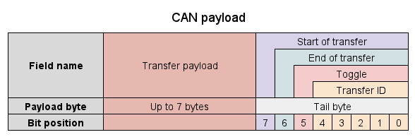
The tail byte contains the following fields, starting from the most significant bit:
| Field | Bits | Description |
|---|---|---|
| Start of transfer | 1 | See below |
| End of transfer | 1 | See below |
| Toggle bit | 1 | See below |
| Transfer ID | 5 | The transfer ID value |
The following figure summarizes the data field format for a single-frame transfer:
![]()
The following figure summarizes the data field format for a multi-frame transfer:
![]()
Start of transfer
For single-frame transfers, the value of this field is always 1.
For multi-frame transfers, the value of this field is 1 if the current frame is the first frame of the transfer, and 0 otherwise.
End of transfer
For single-frame transfers, the value of this field is always 1.
For multi-frame transfers, the value of this field is 1 if the current frame is the last frame of the transfer, and 0 otherwise.
Toggle bit
For single-frame transfers, the value of this field is always 0.
For multi-frame transfers, this field contains the value of the toggle bit. As specified above this will alternate value between frames, starting at 0 for the first frame.
Transfer ID
This field contains the transfer ID value of the current transfer (for all types of transfers).
The value is 5 bits wide, therefore the allowed values range from 0 to 31, inclusively.
Reception
Transfer ID comparison
The following explanation relies on the concept of transfer ID forward distance. Transfer ID forward distance is a function of two transfer ID values, A and B, that defines the number of increment operations that need to be applied to A so that A’ equals B. Consider an example:
- A = 0, B = 0 ⇒ forward distance 0
- A = 0, B = 5 ⇒ forward distance 5
- A = 31, B = 30 ⇒ forward distance 31 (overflow)
- A = 31, B = 0 ⇒ forward distance 1 (overflow)
The following code sample provides an implementation of the transfer ID comparison algorithm in C++:
/*
 * License: CC0, no copyright reserved.
 */

#include <cstdint>
#include <iostream>
#include <cassert>

constexpr std::uint8_t TransferIDBitLength = 5;

std::int8_t computeForwardDistance(std::uint8_t a, std::uint8_t b)
{
    constexpr std::uint8_t MaxValue = (1U << TransferIDBitLength) - 1U;
    assert((a <= MaxValue) && (b <= MaxValue));

    std::int16_t d = static_cast<std::int16_t>(b) - static_cast<std::int16_t>(a);
    if (d < 0)
    {
        d += 1U << TransferIDBitLength;
    }

    assert((d <= MaxValue) && (d >= -MaxValue));
    assert(((a + d) & MaxValue) == b);
    return static_cast<std::int8_t>(d);
}

int main()
{
    assert(0  == computeForwardDistance(0, 0));
    assert(1  == computeForwardDistance(0, 1));
    assert(7  == computeForwardDistance(0, 7));
    assert(0  == computeForwardDistance(7, 7));
    assert(31 == computeForwardDistance(31, 30)); // overflow
    assert(1  == computeForwardDistance(31, 0));  // overflow
}
Half range of transfer ID is 16.
State variables
A node that can receive a transfer must keep a certain set of state variables for each transfer descriptor. The set of state variables will be referred to as receiver state. For the purposes of specification, it is assumed that the node will maintain a mapping from transfer descriptors to receiver states, which is referred to as the receiver map.
The receiver state should include at least the following variables:
| State | Description |
|---|---|
| Transfer payload | Actual payload of the transfer |
| Transfer ID | Transfer ID value |
| Next toggle bit | Expected value of the toggle bit in the next frame of the transfer |
| Transfer timestamp | The local time when the first frame of the transfer arrived |
| Interface index | Only applicable for a redundant interface configuration |
The following operations are defined for the receiver state:
- Add data to the payload - this operation adds new data to the current transfer’s payload state.
- Reinitialize - this operation resets the state variables to match the parameters of a new transfer.
Reinitialization includes at least the following:
- Clearing the transfer payload;
- Updating the transfer ID value with the actual value from the new transfer;
- Clearing the toggle bit;
- Initializing the transfer timestamp;
- Initializing the interface index, if applicable.
The following conditions are defined for the receiver state:
- Uninitialized - this is a default condition, which indicates that the receiver has not yet seen any transfers.
- Transfer ID timeout - last matching transfer was seen more than 2 seconds ago.
- Interface switch allowed - this condition is only applicable for configurations with redundant CAN bus interfaces. It means that the node is allowed to receive the next transfer from an interface that is not the same as the one the previous transfer was received from. The condition will be reached if the last matching transfer has been successfully received more than Tswitch seconds ago. The value of Tswitch must not exceed 2 seconds. The actual value of Tswitch can be either a constant chosen by the designer according to the application requirements (e.g., maximum recovery time in an event of an interface failure), or the protocol stack may estimate the value automatically by means of analysing the transfer intervals.
Whenever a node receives a transfer, it will query its receiver map for the matching transfer descriptor. If the matching state does not exist, the node will add a new uninitialized receiver state to the map. The node then will proceed with the procedure of receiver state update, which is defined below.
It is expected that some transfers will be aperiodic or ad-hoc, which implies that the receiver map may accumulate receiver states that are no longer used over time. Therefore, nodes are allowed, but not required, to remove any receiver state from the receiver map, once the state reaches the transfer ID timeout condition.
Receiver state can only be modified when a new CAN frame of a matching transfer is received. This guarantee simplifies implementation, as it implies that the receiver states will not require any background maintenance processes.
State update in a redundant interface configuration
The following pseudocode demonstrates the transfer reception process for a configuration with redundant CAN bus interfaces.
// Constants:
tid_timeout := 2 seconds;
tid_half_range := 16;
iface_switch_delay := UserDefinedConstant; // Or autodetect

// State variables:
initialized := 0;
payload;
this_transfer_timestamp;
current_transfer_id;
iface_index;
toggle;

function receiveFrame(frame)
{
    // Resolving the state flags:
    tid_timed_out := (frame.timestamp - this_transfer_timestamp) > tid_timeout;
    same_iface := frame.iface_index == iface_index;
    first_frame := frame.start_of_transfer;
    non_wrapped_tid := computeForwardDistance(current_transfer_id, frame.transfer_id) < tid_half_range;
    not_previous_tid := computeForwardDistance(frame.transfer_id, current_transfer_id) > 1;
    iface_switch_allowed := (frame.timestamp - this_transfer_timestamp) > iface_switch_delay;

    // Using the state flags from above, deciding whether we need to reset:
    need_restart :=
        (!initialized) or
        (tid_timed_out) or
        (same_iface and first_frame and not_previous_tid) or
        (iface_switch_allowed and first_frame and non_wrapped_tid);

    if (need_restart)
    {
        initialized := 1;
        iface_index := frame.iface_index;
        current_transfer_id := frame.transfer_id;
        payload.clear();
        toggle := 0;
        if (!first_frame)
        {
            current_transfer_id.increment();
            return;                       // Ignore this frame, since the start of the transfer has already been missed
        }
    }

    if (frame.iface_index != iface_index)
    {
        return;  // Wrong interface, ignore
    }

    if (frame.toggle != toggle)
    {
        return;  // Unexpected toggle bit, ignore
    }

    if (frame.transfer_id != current_transfer_id)
    {
        return;  // Unexpected transfer ID, ignore
    }

    if (first_frame)
    {
        this_transfer_timestamp := frame.timestamp;
    }

    toggle := !toggle;
    payload.append(frame.data);

    if (frame.last_frame)
    {
        // CRC validation for multi-frame transfers is intentionally omitted for brevity
        processTransfer(payload, ...);

        current_transfer_id.increment();
        toggle := 0;
        payload.clear();
    }
}
State update in a non-redundant interface configuration
The following pseudocode demonstrates the transfer reception process for a configuration with a non-redundant CAN bus interface.
// Constants:
tid_timeout := 2 seconds;

// State variables:
initialized := 0;
payload;
this_transfer_timestamp;
current_transfer_id;
toggle;

function receiveFrame(frame)
{
    // Resolving the state flags:
    tid_timed_out := (frame.timestamp - this_transfer_timestamp) > tid_timeout;
    first_frame := frame.start_of_transfer;
    not_previous_tid := computeForwardDistance(frame.transfer_id, current_transfer_id) > 1;

    // Using the state flags from above, deciding whether we need to reset:
    need_restart :=
        (!initialized) or
        (tid_timed_out) or
        (first_frame and not_previous_tid);

    if (need_restart)
    {
        initialized := 1;
        current_transfer_id := frame.transfer_id;
        payload.clear();
        toggle := 0;
        if (!first_frame)
        {
            current_transfer_id.increment();
            return;                       // Ignore this frame, since the start of the transfer has already been missed
        }
    }

    if (frame.toggle != toggle)
    {
        return;  // Unexpected toggle bit, ignore
    }

    if (frame.transfer_id != current_transfer_id)
    {
        return;  // Unexpected transfer ID, ignore
    }

    if (first_frame)
    {
        this_transfer_timestamp := frame.timestamp;
    }

    toggle := !toggle;
    payload.append(frame.data);

    if (frame.last_frame)
    {
        // CRC validation for multi-frame transfers is intentionally omitted for brevity
        processTransfer(payload, ...);

        current_transfer_id.increment();
        toggle := 0;
        payload.clear();
    }
}
CAN bus requirements
The chapter dedicated to hardware design recommendations contains important information concerning CAN bus bit rate, connectors, and other properties of the physical layer of the protocol.
CAN controller driver software
Multi-frame transfers use identical CAN ID for all frames of the transfer, and UAVCAN requires that all frames of a multi-frame transfer should be transmitted in order. Therefore, the CAN controller driver software must ensure that CAN frames with identical CAN ID must be transmitted in their order of appearance in the TX queue. Some hardware will not meet this requirement by default, so the designer must take special care to ensure correct behavior, and apply workarounds if necessary.