Hardware design recommendations
This chapter contains best-practice recommendations for hardware design.
Following these guidelines will ensure the highest level of inter-vendor compatibility and allow the developers to avoid many common design pitfalls.
Physical connector definition

The UAVCAN standard defines several connector types, targeted towards different application domains: from highly compact systems to large deployments, from low-cost to safety-critical applications.
The following table provides an overview of the currently defined connector types. The image to the right comparatively demonstrates the size of the connector types.
Other connector types may be added in future revisions of the specification.
| Connector name | Base connector type | Bus power | Known compatible standards |
|---|---|---|---|
| UAVCAN D-Sub | Generic D-Subminiature DE-9 | 24 V, 3 A | De-facto standard connector for CAN, supported by many current specifications |
| UAVCAN M8 | Generic M8 5-circuit B-coded | 24 V, 3 A | CiA 103 (CANopen) |
| UAVCAN Micro | JST GH 4-circuit | 5 V, 1 A | Dronecode Autopilot Connector Standard |
UAVCAN D-Sub connector
The UAVCAN D-Sub connector type is based upon, and compatible with, the D-Subminiature DE-9 CAN connector (this is the most popular CAN connector type, in effect the de-facto industry standard). This connector is fully compatible with CANopen and many other current specifications.
Advantages
- Highest level of compatibility with the existing commercial off the shelf (COTS) hardware. Connectors, cables, termination plugs, and other components can be easily purchased from many different vendors.
- High-reliability options are available from multiple vendors.
- Low-cost options are available from multiple vendors.
- PCB mounted and panel mounted types are available.
Disadvantages
D-Subminiature connectors are the largest connector type defined by UAVCAN. Due to its significant size and weight, it may be unsuitable for many vehicular applications.
Specification
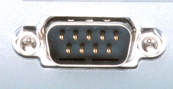
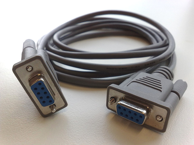
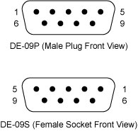
The UAVCAN D-Sub connector is based on the industry-standard D-Sub DE-9 (9-circuit) connector type. Devices are equipped with the male plug connector type (see the image) mounted on the panel or on the PCB, and the cables are equipped with the female socket connectors on both ends.
If the device uses two parallel connectors per CAN bus interface (as recommended), then all of the lines of the paired connectors, including those that are not used by the current specification, must be interconnected one to one. This will ensure compatibility with future revisions of the specification that make use of currently unused circuits of the connector.
The CAN physical layer standard that can be used with this connector type is ISO 11898-2, also known as high-speed CAN.
Devices that deliver power to the bus are required to provide 23.0—30.0 V on the bus power line, 24 V nominal. The maximum current draw is up to 3 A per connector.
Devices that are powered from the bus should expect 18.0—30.0 V on the bus power line. The maximum recommended current draw from the bus is 500 mA per device.
The table below documents the pinout specification for the UAVCAN D-Sub connector type.
The provided pinout, as has been indicated above, is the de-facto industry standard for the CAN bus.
Note that the signals CAN High and CAN Low must belong to the same twisted pair.
Usage of twisted or flat wires for all other signals remains at the discretion of the implementer.
| Circuit number | Function | Note |
|---|---|---|
| 1 | Reserved for future use. | |
| 2 | CAN Low | Twisted with CAN High (pin 7). |
| 3 | CAN Ground | Must be interconnected with Ground (pin 6) within the device. |
| 4 | Reserved for future use. | |
| 5 | CAN Shield | Optional. |
| 6 | Ground | Must be interconnected with CAN Ground (pin 3) within the device. |
| 7 | CAN High | Twisted with CAN Low (pin 2). |
| 8 | Error line, not used by UAVCAN. See CiA 303 for details. | |
| 9 | Bus power supply | 24 V nominal. Power supply requirements are documented above. |
UAVCAN M8 connector
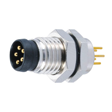
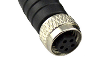
The UAVCAN M8 connector is based on the standard circular M8 B-coded 5-circuit connector type (pictured). This is a popular industry-standard connector, and there are many vendors that manufacture compatible components: connectors, cables, termination plugs, T-connectors, and so on. The pinning, physical layer, and supply voltages used in this connector type are compatible with CiA 103 (CANopen) and some other CAN bus standards.
The M8 connector is preferred for most UAVCAN applications (it is the default choice, except when there are specific reasons to select another connector).
Advantages
- Compatibility with existing COTS hardware. Connectors, cables, termination plugs, and other components can be purchased from many different vendors.
- High-reliability options are available from multiple vendors.
- Low-cost options are available from multiple vendors.
- Reasonably compact. M8 connectors are much smaller than D-Sub.
- PCB mounted and panel mounted types are available.
Disadvantages
- M8 connectors may be a poor fit for applications that have severe weight and space constraints.
- The level of adoption in the industry is noticeably lower than that of the D-Sub connector type.
Specification
The UAVCAN M8 connector is based on the industry-standard circular M8 B-coded 5-circuit connector type. Devices are equipped with the male plug connector type (see the image) mounted on the panel or on the PCB, and the cables are equipped with the female socket connectors on both ends. Do not confuse A-coded and B-coded M8 connectors — they are not mutually compatible.
The CAN physical layer standard that can be used with this connector type is ISO 11898-2, also known as high-speed CAN.
Devices that deliver power to the bus are required to provide 23.0—30.0 V on the bus power line, 24 V nominal. The maximum current draw is up to 3 A per connector.
Devices that are powered from the bus should expect 18.0—30.0 V on the bus power line. The maximum recommended current draw from the bus is 500 mA per device.
The table below documents the pinout specification for the UAVCAN M8 connector type.
The provided pinout, as indicated above, is compatible with the CiA 103 specification (CANopen).
Note that the wires CAN High and CAN Low should be a twisted pair.
| Circuit number | Function | Note |
|---|---|---|
| 1 | Bus power supply | 24 V nominal. Power supply requirements are documented above. |
| 2 | CAN Shield | Optional. |
| 3 | CAN High | Twisted with CAN Low (pin 4). |
| 4 | CAN Low | Twisted with CAN High (pin 3). |
| 5 | Ground |
UAVCAN Micro connector
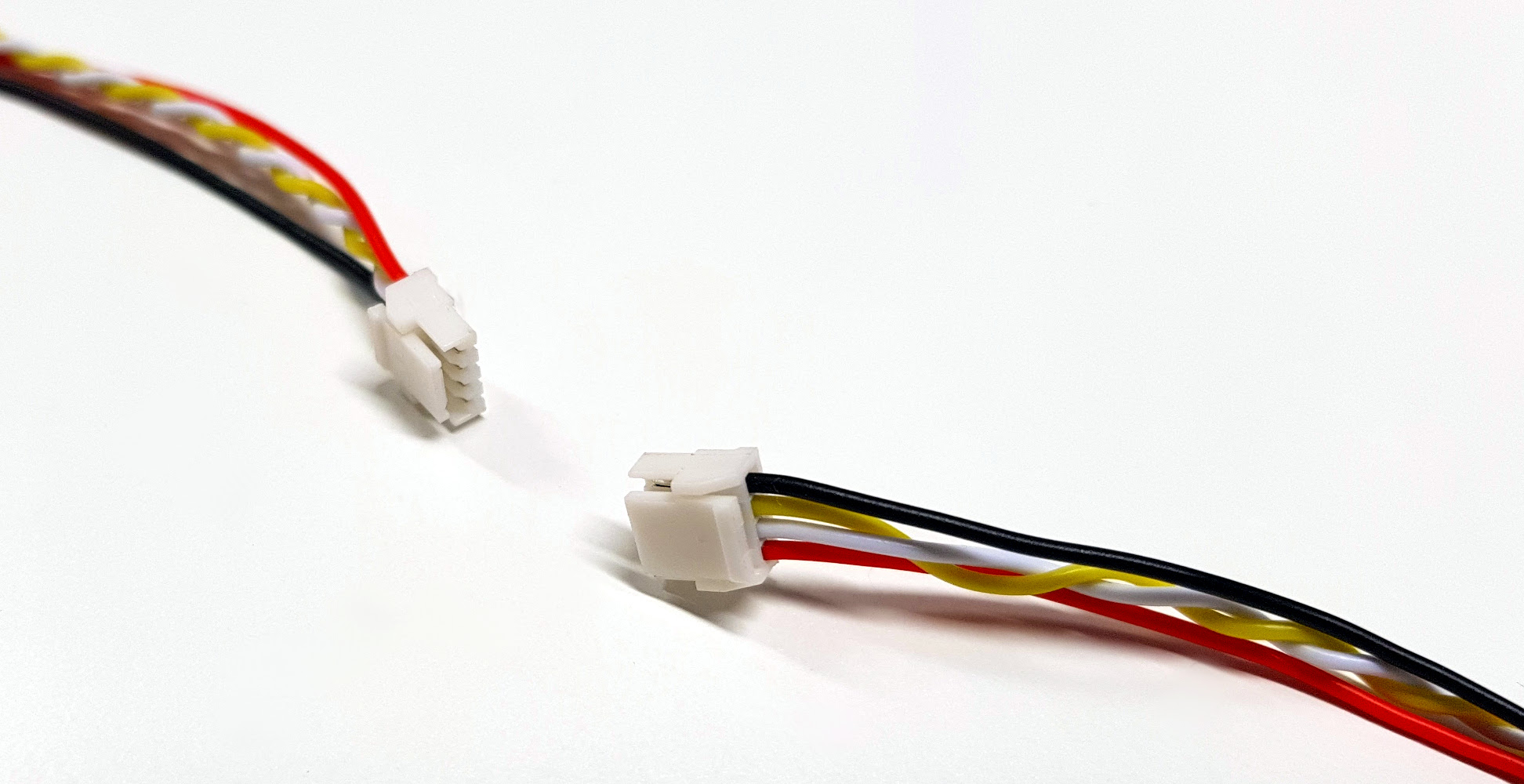
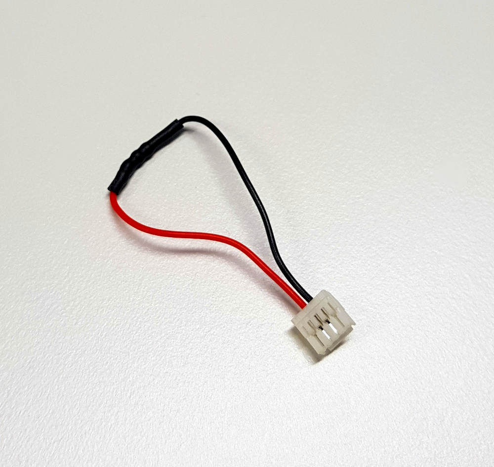
The UAVCAN Micro connector is intended for weight- and space-sensitive applications. It is a board-level connector, meaning that it can be installed on the PCB rather than on the panel.
The Micro connector is compatible with the Dronecode Autopilot Connector Standard. This connector type is recommended for small UAV and nanosatellites. It is also the recommended connector for attaching external panel-mounted connectors (such as the M8 or D-Sub types) to the PCB inside the enclosure.
Advantages
- Extremely compact, low-profile. The PCB footprint is under 9✕5 millimeters.
- Secure positive lock ensures that the connection will not self-disconnect when exposed to vibrations.
- Low-cost, easy to stock.
Disadvantages
- Board-level connections only. No panel-mounted options available.
- No shielding available.
- Not suitable for safety-critical hardware.
Specification
The Micro connector is based on the proprietary JST GH 4-circuit connector type.
The suitable cable types are flat or twisted pair #30 to #26 AWG, outer insulation diameter 0.8—1.0 mm, multi-strand. Non-twisted (flat) cables can only be used in very small deployments free of significant EMI, otherwise reliable functioning of the bus cannot be guaranteed.
The CAN physical layer standard that can be used with this connector type is ISO 11898-2, also known as high-speed CAN.
Devices that deliver power to the bus are required to provide 5.0—5.5 V on the bus power line. The anticipated current draw is up to 1 A per connector.
Devices that are powered from the bus should expect 4.0—5.5 V on the bus power line. The maximum recommended current draw from the bus is 500 mA per device.
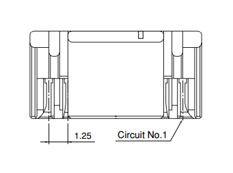
| Circuit number | Function | Recommended wire designation for 25-pair-color-coded cables |
|---|---|---|
| 1 | Bus power supply |  pair 1 tip pair 1 tip |
| 2 | CAN High |  pair 2 ring pair 2 ring |
| 3 | CAN Low |  pair 2 tip pair 2 tip |
| 4 | Ground |  pair 1 ring pair 1 ring |
Design recommendations
Connectors
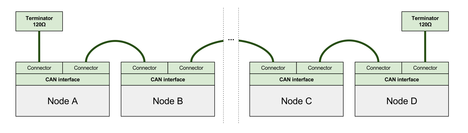
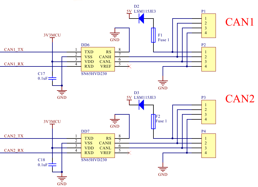
It is highly recommended to provide two identical parallel connectors for each CAN interface per device, so that the device can be connected to the bus without the need to use T-connectors. T-connectors should be avoided when possible because generally they add an extra point of failure, increase the stub length, weight, and often require more complex and expensive wiring harnesses.
The figure below demonstrates a CAN bus wired according to the above recommendation.
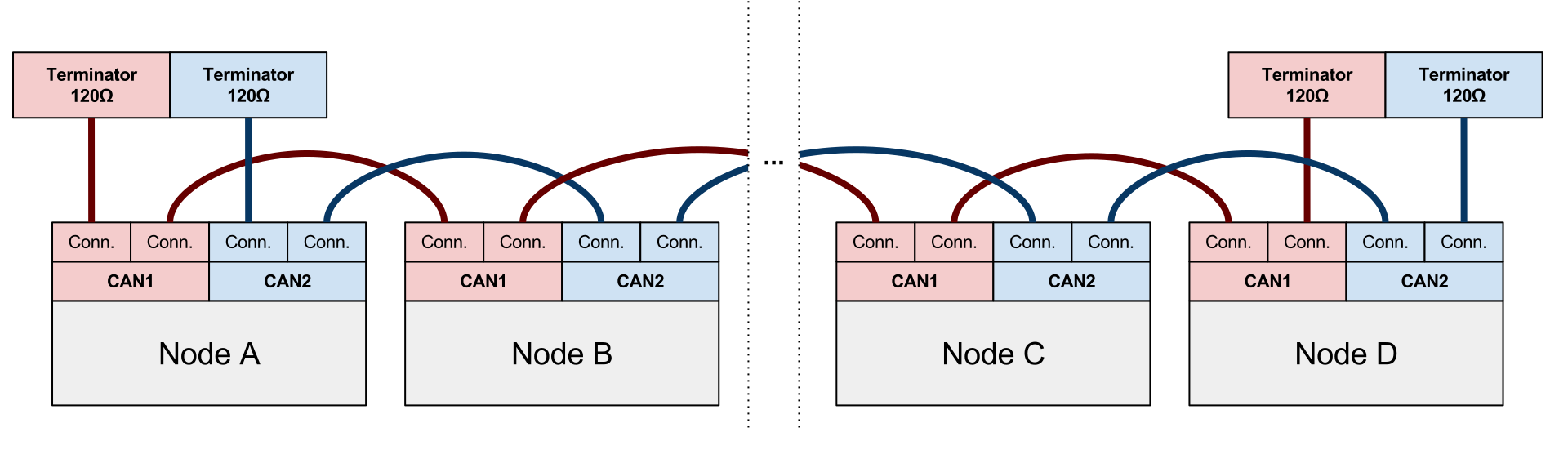
The next figure shows a bus where the devices are equipped with doubly redundant interfaces. The same principles apply to a triply-redundant bus as well.
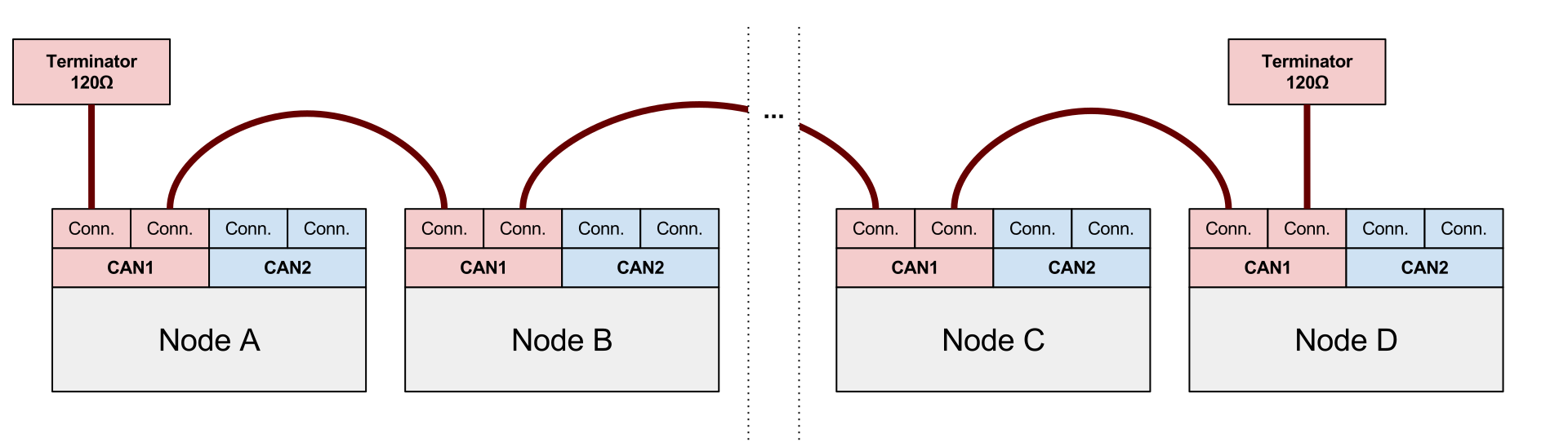
UAVCAN permits keeping one of the redundant interfaces unused. An example of such wiring is shown on the following figure.
Devices with different number of redundant interfaces
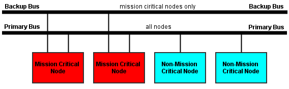
Mission critical devices and non-mission critical devices often need to co-exist on the same UAVCAN network. Non-mission critical devices are likely to be equipped with a non-redundant CAN bus interface, which can create the situation where multiple devices with a different number of redundant interfaces need to be connected to the same UAVCAN network.
If multiple devices with a different number of interfaces need to co-exist on the same UAVCAN network, the following rules should be followed:
- Each available CAN bus (UAVCAN supports up to 3) is assigned a level of importance (primary or backup).
- All devices should be connected to the primary CAN bus.
- Only devices with redundant interfaces should be also connected to the backup bus/buses.
The figure below shows a doubly redundant CAN bus, but the same considerations apply to a triply redundant bus:
Bus power supply
Bus-powered devices
This section applies to devices that draw power from the bus.
Each power input must be protected with an overcurrent protection circuit (for example, a fuse), so that an accidental short circuit on the device will not bring down the power on the entire bus.
If the device incorporates redundant bus interfaces, it must prevent direct current flow between power inputs from different interface connectors, so that if one bus suffers a power failure (e.g. a short circuit) it won’t be propagated to other buses.
Bus-powering devices
This section applies to devices that deliver power to the bus.
Similar to the case of bus-powered devices, UAVCAN power sources should take into account that one of the redundant interfaces may suffer a short circuit or a failure of similar mode. Should that happen, the power source should shut down the failing bus and continue to supply the remaining bus interfaces.
CAN bus parameters
UAVCAN is bit rate agnostic, so technically any bit rate can be used as long as it is supported by the physical layer. However, only the recommended bit rates from the table below should be used to ensure compatibility.
All recommended bit rates and other relevant CAN bus parameters are listed in the table below.
| Bit rate | Valid range for location of sample point | Recommended location of sample point | Max bus length | Max stub length |
|---|---|---|---|---|
| 1000 kbit/s | 75% to 90% | 87.5% | 40 m | 0.3 m |
| 500 kbit/s | 85% to 90% | 87.5% | 100 m | 0.3 m |
| 250 kbit/s | 85% to 90% | 87.5% | 250 m | 0.3 m |
| 125 kbit/s | 85% to 90% | 87.5% | 500 m | 0.3 m |
The estimated bus length limits are based on the assumption that the propagation delay does not exceed 5 ns/m, not including additional delay times of CAN transceivers and other components.
Automatic bit rate detection
Designers are encouraged to implement CAN auto bit rate detection when applicable. Please refer to the CiA 801 application note for recommended practices.
UAVCAN enables the use of the simple bit time measuring approach, as it is guaranteed that any functioning UAVCAN network will always exchange node status messages, which can be expected to be published at a rate no lower than 1 Hz, and that contain a suitable alternating bit pattern in the CAN ID field. Please refer to the chapter dedicated to the application-level functions for details.
See also
- Controller Area Network Physical Layer Requirements (Application Report, SLLA270–January 2008)
- CAN and CAN-FD a brief tutorial (www.computer-solutions.co.uk)
- CAN CiA Specifications (www.can-cia.org)